
 English
 русский
 中文简体
中文简体
RILSON GASKET
Ningbo Rilson Sealing Material Co., Ltd is dedicated to ensuring the secure and dependable operation of fluid sealing systems, offering clients the appropriate sealing technology solutions.
You shut down a pump train for a routine inspection, and when the blind flange comes off, you see a 0.3 mm deep radial scratch across the sealing face. The maintenance plan says replace the gasket, but does the flange itself need machining or replacement? For pumps, compressors, and piping systems in petrochemical service, this question comes up every time a flange face shows wear. ASME PCC-1 provides an accepted answer: the decision depends on the defect depth, the gasket type, and the pressure class of the joint. Executing that decision correctly is the difference between a joint that lasts a full turnaround and one that starts leaking during startup.
Content
ASME PCC-1 is the leading guideline for bolted flange joint assembly, and its Appendix on flange face acceptance gives a practical threshold for damage. For scratches, gouges, and pits on the gasket seating surface, the generally accepted maximum depth is 1/32 inch, or 0.8 mm, provided that the defect does not extend beyond the sealing face width and does not affect the flatness of the raised face.
When the defect depth is below 0.8 mm and the surface finish remains within the specified Ra range for the gasket type, the flange can usually be accepted as-is. If the damage exceeds that limit, the flange may need repair by machining or metal build-up, or replacement if the wall thickness or pressure rating is compromised.
The chart below compares the ASME PCC-1 acceptance limit with the point at which repair is typically required. This is a simplified visual aid based on the standard's threshold:
In practice, this threshold is not a blanket approval. The actual acceptability depends on the service pressure, the gasket hardness, and the location of the defect relative to the bolt circle. A shallow scratch on the outer edge may be harmless, while the same scratch crossing the raised face can create a leak path.
Field assessment does not require expensive ultrasonic or profilometer equipment for most cases. A straightedge and a feeler gauge check the flatness of the raised face, and a dial indicator or depth gauge measures the depth of a gouge or pit. Always inspect the full circumference, especially near bolt holes where crevice corrosion tends to start.
The isometric diagram below illustrates typical defect locations on a raised face flange. The red arrows point to areas where the sealing surface is most vulnerable: radial scratches, diagonal gouges, and localized pits.
When a defect is found, clean the surface with a non-metallic scraper and verify that the depth is measured before any repair. Use a ball-point marker to trace the defect outline, then run a depth gauge across the trace to confirm the largest depth reading. Document the results with a photo and a record of the gasket type that will be installed.
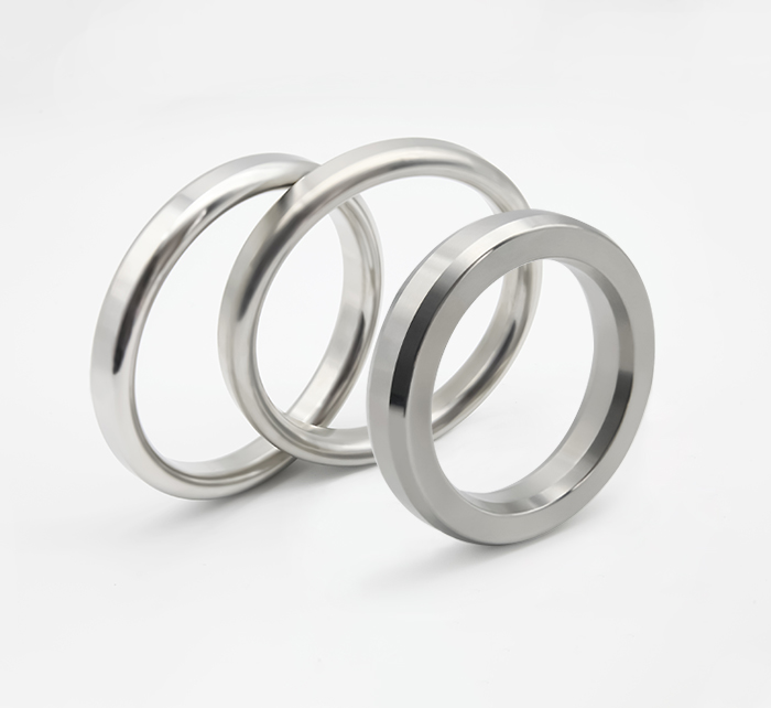
Ring joint gaskets used on RTJ flanges are especially sensitive to groove damage. A scratched or pitted groove can easily create a leak path that is not visible to the eye, so a detailed groove inspection is mandatory before re-installation.
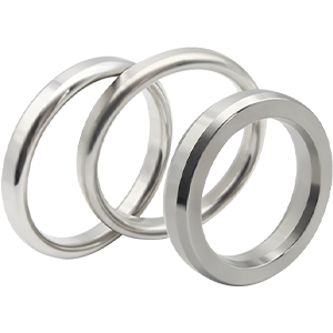 Ring Joint GasketsRing Type Joint Gaskets are developed for use in the petroleum industry as well as drilling and oil gas production equipment. These gaskets are suitable for the high p...View Product →
The quickest way to decide is to compare the defect depth against the 0.8 mm threshold and check the position relative to the raised face. The table below summarizes the typical actions for common flange face conditions.
| Condition | Typical defect depth | Recommended action |
|---|---|---|
| Minor scratches on outer edge | < 0.8 mm | Accept and install new gasket |
| Gouge crossing the raised face | 0.8 mm or less | Accept if surface finish is within Ra, otherwise lap |
| Deep pit near bolt holes | > 0.8 mm | Repair by machining or metal build-up |
| Corrosion attack over wide area | Varies | Replace flange if wall thickness is reduced |
In one petrochemical reference, a scratch depth of 0.8 mm was accepted without repair when the flange was used with a spiral wound gasket at 150 lb pressure class. However, the same damage on a high-pressure class 900 flange would demand repair. Always check the gasket seating width and the service rating before accepting a surface.
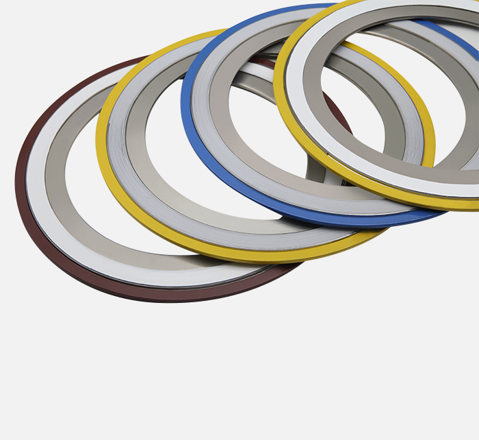
For many flanged joints, choosing a spiral wound gasket with a flexible graphite filler can compensate for minor surface imperfections that remain within the ASME PCC-1 acceptance limit.
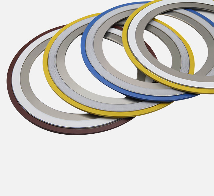 Spiral Wound GasketsSpiral Wound Gaskes t with PTFE fillerView Product →
For detailed information on how flange surface finish and condition affect the sealing performance of spiral wound gaskets, refer to this practical guide.
If the flange face has minor damage that still falls within the ASME PCC-1 acceptance limit, the gasket type has a direct impact on joint reliability. Softer gaskets can conform to small surface irregularities, while metal-to-metal gaskets require a near-perfect surface.
The chart below compares the relative tolerance of common gasket types to minor flange face damage, based on typical industrial practice. The higher the bar, the more tolerant the gasket is to surface imperfections.
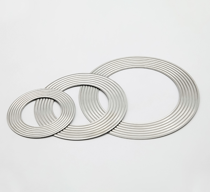
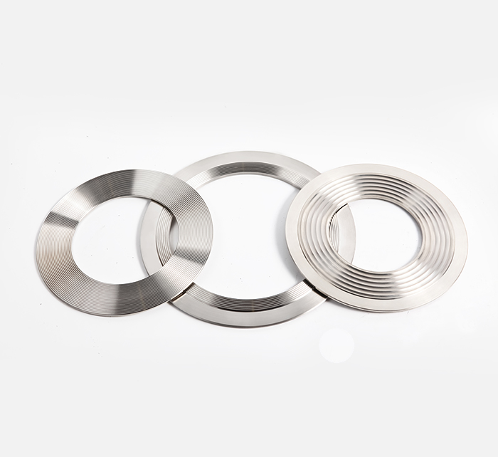
Kammprofile gaskets are often specified when a flange face has light scratches but the flatness is still acceptable. Their soft sealing layer conforms to minor surface irregularities while the metal core transmits the bolt load.
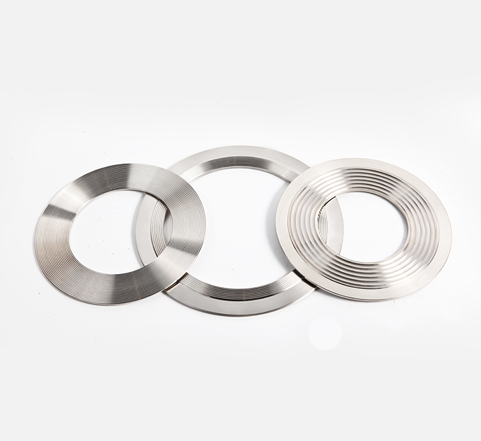 Kammprofile gasketsKammprofile Gasket with Loose Outer RingView Product →
For general service where surface defects are within limits, spiral wound gaskets with a flexible graphite filler adapt well to surface irregularities while maintaining stability at high temperatures and pressures. In contrast, ring joint gaskets are strictly for high-pressure, high-integrity joints and need a clean, defect-free groove.
Most flange face damage is caused during handling and assembly, not during operation. Dropping a flange on a concrete floor, using a damaged gasket, or over-torquing a bolt can all leave permanent marks. Use protective caps on the raised face, clean the studs and nuts, and always use a calibrated torque wrench. When you remove the old gasket, use a non-marring scraper and avoid hammering on the flange surface.
Applying a thin layer of anti-seize compound to the gasket and flange faces can also help prevent galling on repeated assembly, but keep the lubricant well away from the gasket sealing area. Document the bolt-up sequence and target torque values on the job sheet, so the next turnaround starts with a known baseline.
Flange face damage refers to scratches, gouges, pits, or corrosion on the gasket seating surface. ASME PCC-1 identifies acceptance limits for these defects based on depth and location.
ASME PCC-1 generally accepts a defect depth up to 1/32 inch (0.8 mm) for scratches and gouges, provided the surface flatness and finish remain within specification.
If the defect depth is within 0.8 mm and does not affect the sealing width, accept or lightly lap it. If the defect is deeper or extends beyond the raised face, repair by machining or replace.
No. A used gasket has already conformed to the previous flange surface and will not reliably seal a different or damaged surface. Always install a new gasket after any flange work.
ASME B16.5 covers dimensional limits for standard flanges, while ASME PCC-1 focuses on assembly practices, including the acceptability of surface imperfections on the gasket seating area.
Clean the area, use a depth gauge or dial indicator over the scratch path, and take the maximum reading. For rough surfaces, compare with a calibrated reference block.

RILSON GASKET
Ningbo Rilson Sealing Material Co., Ltd is dedicated to ensuring the secure and dependable operation of fluid sealing systems, offering clients the appropriate sealing technology solutions.
Copyright © Ningbo Rilson Sealing Material Co., Ltd. All Rights Reserved.
