
 English
 русский
 中文简体

RILSON GASKET
Ningbo Rilson Sealing Material Co., Ltd is dedicated to ensuring the secure and dependable operation of fluid sealing systems, offering clients the appropriate sealing technology solutions.
Twenty minutes into a hydrotest, a 6-inch raised-face flange starts to weep at its outer edge. The bolts are at the specified torque, the gasket is new, and the pipe was cleaned before assembly. Nothing on the joint looks wrong — and that is usually the point.
Here is the short answer: a flange gasket leak is almost always a joint problem rather than a part problem. The gasket is the softest element in a stack of stiff steel, so it can only seal if the joint gives it three things at the same time: enough residual bolt load, flange faces the gasket can bite into, and a material that survives the real temperature, pressure and medium. Lose any one of those and a leak path opens, often within a single thermal cycle.
The three checks, in order: is the bolt load even and high enough; do the faces match the finish and flatness the gasket needs; and is the gasket class correct for the actual service? Work through them in that order before ordering a different product.
Content
A gasket does not seal by being tight. It seals by being confined: compressed between two faces until it fills the micro-gaps of the surfaces, then held there by the elastic rebound of the bolts. The ASME boiler and pressure vessel design method (Section VIII, Div. 1, Appendix 2) reduces this to two factors — a seating stress y to establish initial contact and a maintenance factor m to keep contact under internal pressure. When residual load drops below what the gasket needs, the joint stops being a barrier.
That is why the same gasket style holds for years on one line and fails in a week on another. A leak is the visible end of a slow loss of load, a surface that never matched the gasket, or a medium that attacked the binder.
Schematic trend, not measured data: leakage falls as load rises, bottoms out inside the design window, then climbs again once the gasket is crushed or the flanges rotate.
Field investigations tend to collapse into a short list. Naming the failure path first saves the most time, because each path has one decisive check.
| Failure path | What you usually see | Check first |
|---|---|---|
| Uneven or low bolt load | Leak on one side only; gasket compressed on one arc, untouched opposite | Tightening sequence, lubricant, torque wrench calibration |
| Face damage or wrong finish | Radial scratches from bore to bolt circle; shiny or torn face | Ra and Rz, flatness, straight-edge check |
| Wrong gasket class | Early failure, gasket brittle, crushed or extruded | Datasheet limits against real temperature, pressure, medium |
| Installation error | Cut, twisted or reused gasket; dirt trapped under the ring | Assembly record and witness marks on the old gasket |
| Thermal cycling and relaxation | Leak appears during heat-up or after a shutdown | Whether a re-torque was scheduled after first heat-up |
| Piping strain and vibration | Flange faces no longer parallel; gap changes with line temperature | Alignment, support spacing, cold spring |
Three routes matter, and investigators often chase only the first. A face leak crosses between the gasket and the flange. Body permeation passes through the gasket material itself — the usual culprit with fine media such as hydrogen or low-molecular-weight gases. The third route is not a path through the gasket at all: the bolt load simply relaxes away, and the joint opens.
Ra decides whether a gasket can grip. Too rough and the gasket cannot bridge the peaks; too smooth and a sheet gasket has nothing to bite, so it creeps sideways under load. Each gasket class expects its own window, and the window is narrower than most drawings suggest.
Typical specification ranges for machined faces; confirm the exact window on the gasket datasheet and the flange standard (ASME B16.5 or EN 1092-1).
Two details matter as much as the average. First, Rz — a face can hit its Ra target and still leak if peak-to-valley roughness is high. Second, direction: radial scratches running from the bore out to the bolt circle form a straight channel across the sealing band, while concentric machining marks rarely do. A polished face is not automatically a better face, and a rough one is not automatically worse; what matters is agreement between the gasket and the surface. Our note on how flange surface finish affects spiral wound gasket sealing covers the same point in more depth.
Torque values are a common blind spot. Work on bolted joints has long shown that friction alone scatters preload by roughly 25–30% for a given torque (Bickford, An Introduction to the Design and Behavior of Bolted Joints), so a calibrated wrench guarantees the torque, not the load.
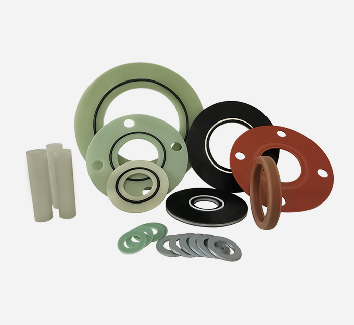
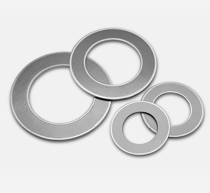
Selection should follow the service, not the last purchase order. As a working rule: sheet gaskets suit low-pressure utility service on good faces; spiral wound covers steam, hydrocarbon and moderate-to-high pressure duties; kammprofile handles cyclic and high-temperature joints where a thin, metal-backed gasket resists relaxation; and ring joint gaskets belong to high-pressure, API-style applications where the seal is metal-to-metal inside a precision groove.
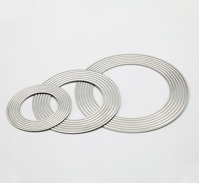
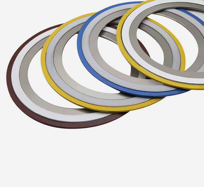
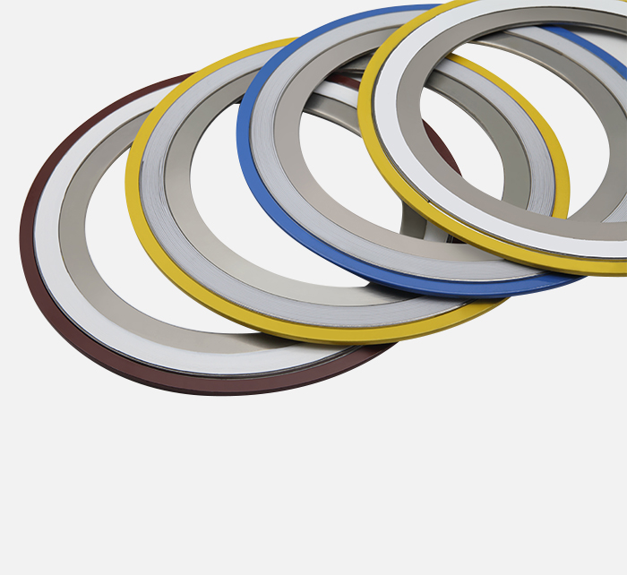 Spiral Wound Gaskets for Steam and Hydrocarbon ServiceExplore styles, rings, metals and fillers for moderate-to-high pressure sealing, with guidance on selection and installation.View Product →
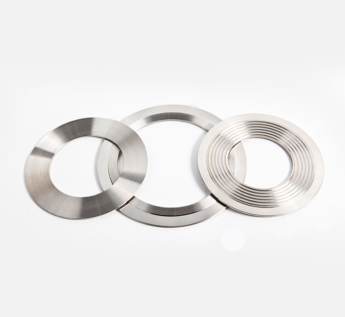
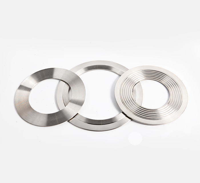 Kammprofile Gaskets for High-Pressure and High-Temperature JointsReview serrated metal cores, graphite or PTFE facings, and RK styles for cyclic, high-temperature sealing where conventional gaskets may distort or displace.View Product →
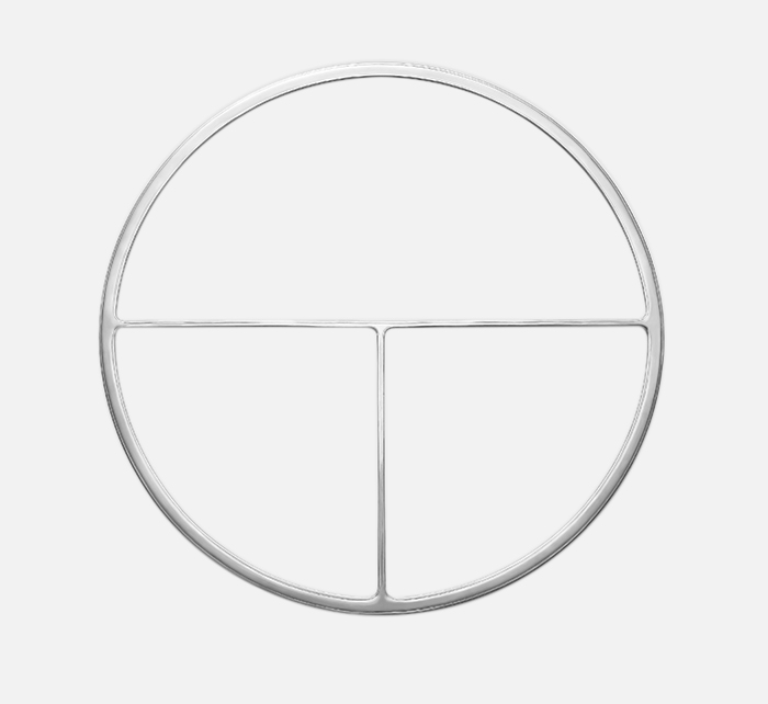
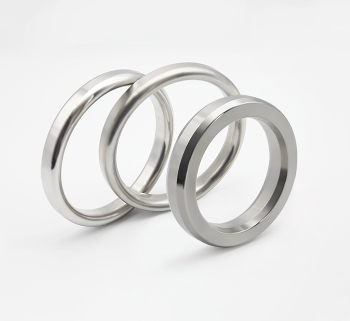
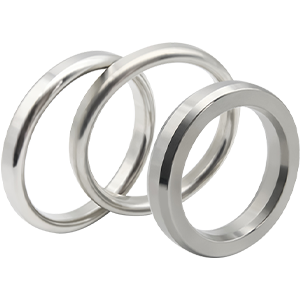 Ring Joint Gaskets for High-Pressure Oil and Gas ServiceCompare R, RX, BX and lens ring styles, metal options and API-standard configurations for metal-to-metal sealing in precision flange grooves.View Product →
Installation decides whether that choice holds. Clean and inspect both faces, fit a new gasket every time, lubricate stud threads and nut faces with a product compatible with the service temperature, and bring the joint up in crossed passes. Where graphite or PTFE-based materials are involved, a re-torque after the first thermal cycle recovers most of the load lost to consolidation.
The exhaust flange gasket on a car or truck obeys the same rules. Two or three studs, a soft gasket and constant thermal cycling; when the joint opens you get a tick at idle that becomes a roar under load. Doubling gaskets or packing the joint with sealer sometimes quietens it for a while, but the underlying cause is usually a warped or eroded flange face or a corroded fastener that can no longer hold load. Repair the faces, replace the fasteners, torque evenly — and the leak stays away far longer than any sealant will manage.
Insufficient or uneven bolt load, followed by a flange face that does not match the gasket's finish requirement. Material failure comes third, not first.
Rarely for long. Extra torque on one side rotates the flange and unloads the opposite arc, so the leak moves rather than closes. If the cause is material or a damaged face, more torque accelerates the failure.
The value comes from the gasket seating stress, bolt size and friction conditions — not from a generic table. Use the gasket maker's figures, apply them in crossed passes, and record the lubricant used, because friction changes the load for the same torque.
Consolidation and thermal expansion reduce residual load in the first heat cycle. A scheduled re-torque, correct compression ring thickness and a face finish within the specified Ra range usually prevent it.
Typically 3.2–6.3 µm Ra for sheet and spiral wound gaskets and 0.8–1.6 µm for ring joint grooves, with no radial scratches and acceptable flatness across the face.
Warped or corroded flange faces, stretched or rusted studs, and repeated heat cycles that relax the joint. Replacing the gasket without correcting faces and fasteners leads to a repeat leak.

RILSON GASKET
Ningbo Rilson Sealing Material Co., Ltd is dedicated to ensuring the secure and dependable operation of fluid sealing systems, offering clients the appropriate sealing technology solutions.
Copyright © Ningbo Rilson Sealing Material Co., Ltd. All Rights Reserved.
